
 Larger view
|
This array of feed horns allows us to detect radio signals from 7 points on the
sky simultaneously; hence it produces, for each pointing, an image with 7 pixels.
ALFA was constructed at the ATNF in Australia. To the left is a photo
taken when it was first being tested there, before being shipped to Puerto Rico.
The bottom white cylindrical container holds the radio amplifiers; they are kept
cooled to about 3K. The shaped golden cylinders higher up are the seven
feed horns.
After being shipped to Puerto Rico, ALFA was hoisted from the bottom of the telescope dish to the platform above. The photo to the right shows ALFA during the lift. |
 Larger view
|
|
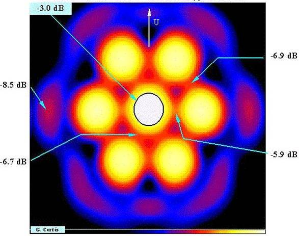
The beam pattern of the ALFA array is its diffraction pattern and dictates its sensitivity and resolution. The image to the left illustrates the sensitivity of the entire ALFALFA array to radio radiation from the sky at each pointing. The brightest yellow-white areas represent the peak sensitivity regions of the beams formed by the seven feed horns. The black ellipse visible in the central beam illustrates the locus where the sensitivity falls to 1/2 its peak value for that individual beam. The size of the ellipse is referred to as the half power beam width (HPBW). In fact for ALFA, the beam is somewhat elliptical in shape, with a HPBW of 3.3 x 3.8 arcmin. The figure to the right illustrates the layout of the ALFALFA beampattern as actually measured for the configuration of the array used by ALFALFA. See Giovanelli et al 2005a (Astron. J. 130, 2598) for further details. |